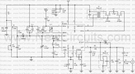
این یک گیرنده سوپر هترودین 27 مگاهرتز با فرکانس کاری 25 تا 28 مگاهرتز:
پیوستها
-
 109 کیلوبایت بازدیدها: 502
آخرین ویرایش توسط مدیر:


با سلام :این یک گیرنده سوپر هترودین 27 مگاهرتز با فرکانس کاری 25 تا 28 مگاهرتز:
با سلام :


| R1, R3, R5 | 100W |
| R2 | 56KW |
| R4 | 39KW |
| R6 | 560W |
| R7, R11 | 6,8KW |
| R8 | 220W |
| R9 | 2,2KW |
| R10 | 5,6KW |
| R12 | 10KW logarithmic pontesiometer |
| R13 | 1KW |
| R14 | 10W |
| C1 | 150pF ceramic |
| C2 | 39pF ceramic |
| C3, C5 | 12pF ceramic |
| C4 | 56pF ceramic |
| C6, C7, C8, C9, C10, C11, C16, C21 | 47nF ceramic |
| C12, C19 | 47mF/16V electrolytic |
| C13, C14 | 10nF ceramic |
| C15 | 100nF polyester |
| C17 | 10mF/16V electrolytic |
| C18 | 2,2mF/16V electrolytic |
| C20 | 470mF/16V electrolytic |
| D1 | AA119, AA117 (germanium diode) |
| Q1, Q2 | BF241 (amplifiers of intermediary frequency) |
| U1 | SO42P (mixed and local oscillator) |
| U2 | LM386 (amplifier A.F.) |
| Y1, Y2 | Crystals hails. (You can you put the so much, those who also channels that you want you touch). See here. |
| MF1 | Medium frequency 455KHz, core yellow. * |
| MF2 | Medium frequency 455KHz, core white. * |
| MF3 | Medium frequency 455KHz, core black. * |
| L1, L2 | Wires of coper (smaltwme'na) with diameter 0,4mm wrapped in plastic support of diameter 6-7mm of perjstrofjkoy' core. For the L1 you wrap 13 coils. For the L2 you wrap 4 coils. |
| LS1 | Loudspeaker 8W/1W. |
| ANT1 | Aerial for CB (For the trials is enough a piece wire of few metres). |
| S1 | Switch of choice of channel. It has so much places, those who also the channels that you want to touch. |
| L | Same with the L1. |
| C | 4 - 40pF trimmer |

| R1 | 10KW |
| R2 | 100KW |
| R3 | 39W |
| R4 | 180W |
| R5 | 4,7KW |
| R6 | 1MW |
| R7 | 3,9KW |
| C1, C9, C10 | 100nF polyester |
| C2 | 33pF ceramic |
| C3 | 470pF ceramic |
| C4 | 4,7nF polyester |
| C5 | 1nF ceramic |
| C6 | 10-60pF trimmer |
| C7 | 220nF polyester |
| C8 | 10mF/25V electrolytic |
| C11 | 47mF/25V electrolytic |
| C12 | 1,5nF ceramic |
| J1, J2, J3 | VK200 (inductor of high frequencies). |
| Wires of coper (smaltwme'na) with diameter 0,4mm wrapped in plastic support of diameter 6-7mm of perjstrofjkoy' core. For the L1 you wrap 13 coils. For the L2 you wrap 4 coils. (As in the receptor CB.) | |
| L3 | Wrap 20 coils cupreous wire of (0,3-0,4mm diameter) convolution round a resistance 2,2W/2W of coal. |
| Q1, Q2 | BC108 |
| Q3 | BD139 |
| Q4 | 2N4427 (it is not replaced) |
| Q5 | BD329 (or 2N3553) |
| Y1, Y2? | Crystal hails. (You can you put the so much, those who also channels that you want you emit). See here. |
| MIC | microphone with preamplifier. |
| ANT1 | Aerial for CB (For the trials is enough a piece wire of few metres but better connects a regular aerial so that does not have many stagnantly and burns the transmitter). |
| S1 | (Choice of receptor of - transmitter, if you combine the transmitter with the receptor CB, you are supplied the receptor from exit 12V OUT) |
| S2 | Switch of choice of channel. It has so much places, those who also the channels that you want pja'nete.(Kaly'tera he is mechanically connected with the S1 of receptor for simultaneous change of channels). |

| R1, R2 | 100W/2W |
| C1 | 47nF ceramic |
| C2 | 4,7nF ceramic |
| J1 | VK200 (inductor of high frequencies). |
| D1 | Passage of germanium (AA119 or OA92 or..). |

با سلام :باسلام من یک فرستنده با برد3کیلو متر می خواهم
