


- 2007-05-09
- 5,023
- 106,550
با سلام :
توسط تلفن از شهر دور و يا { نقطه مقصد } در شهر يا مبدا 9 فرمان مستقلي را اجرا كنيد .
KT3110 اشكارساز DTMF ميباشد با مونتاژ مدار زير ميتوانيد از راه دور تعداد 9 دستگاه را {مستقل از هم } روشن يا خاموش كنيد {بستگي به سليقه و نياز اپراتور ميتوان هر استفاده ديگري كرد } .
ابتدا شمار تلفني كه دستگاه مونتاژ شده در خط ان نصب شده را بگيريد در اين هنگام بعد از دو دريافت دو شبه زنگ دستگاه اتوماتيك فعال شده و اماده دريافت پيام بعدي ميشود حال در صورتيكه بين مكالمه يا به صورت ازاد شمار ديگري بگيريد به نسبت شماره گرفته شده يك رله اي در دستگاه مونتاژي فعال شده و توسط كنتاكت هاي ان فرماني را كه قبلا در محل تعريف كرده ايد اجرا خواهد شد .
درلحظه صدور فرمان براي لحظه اي مدار مكالمه قطع و فرمان صادره دريافت و اجرا ميگردد و بلافاصله خط تلفن اتوماتيك به حالت مكالمه در مياد كه با قطع تلفن مدار فرمانهاي دريافتي را حفظ و اجرا خواهد كرد مدار با 6 ولت باتري يا رگوله شده كامل نياز دارد توضيحات منبع به همراه نقشه و شماتيك و.... ارايه ميگردد .
Description.
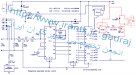
The circuit given below is of a telephone operated DTMF remote. The circuit can be used to switch up to 9 devices using the keys 0 to 9 of the telephone. Digit 0 is used to switch the telephone system between remote switching mode and normal conversation mode. IC KT3170 (DTMF to BCD decoder) is used to decode the DTMF signals transmitted over the telephone line to corresponding BCD format. IC 74154 ( 4 to 16 demultiplexer) and IC CD4023 (dual D flip flop) is used to switch the device according to the receive DTMF signal.
The operation of the circuit is as follows. After hearing the ringtone from the phone at receiver end, press the 0 button of the remote phone. The IC1 will decode this as 1010.The pin 11 of IC2 will go low and after inversion by the NOT gate in IC3 it will be high. This will toggle the flip flop IC5a and the transistor Q1 will be switched on. This will make the relay K1 ON. The two contacts C1 and C2 of the relay K1 will be closed. C1 will form a 220 Ohm loop across the telephone line in order to disconnect the ringer from the telephone line (this condition is similar to taking the telephone receiver off hook).C2 will connect a 10KHz audio source to the telephone line in order to inform you that the system is now in the remote switch mode. Now if you press 1 on the transmitter phone, the IC1 will decode it as 0001 and the pin 2 of IC2 will go low. After inversion by the corresponding NOT gate inside IC3, it will be high. This will toggle flip flop IC5b and transistor Q2 will be switched ON. The relay will be energized and the device connected through its contacts gets switched. Pressing the 1 again will toggle the state of device. In the same ways Keys 2 to 9 on the transmitter phone can be used to toggle the state of the device connected to the channels O2 to O9. After switching is over, press the O key on the transmitter phone in order to toggle the flip flop IC5a to de-energize the relay K1.The 200 Ohm loop will be disconnected from the line, the 10 KHz audio source will be removed and the telephone receiver will be ready to receive new calls.
Notes.
KT3170
The IC KT 3170 used here is a low power DTMF receiver IC from Samsung. The IC is fabricated using low power CMOS technology and can detect all the 16 standard DTMF tones. The DTMF signal received will be decoded to a BCD output for switching applications.
74154
74154 is a 4 line to 16 line decoder from national semiconductors. It decodes a 4 bit input code into one of 16 mutually exclusive outputs. Maximum supply voltage is 7V and normal power dissipation is around 175mW.
CD4049
CD4049 is a CMOS hex inverter from Texas Instruments. Each of the IC contains six NOT gates. Maximum supply voltage possible is 20V and each gate can drive up to two TTL loads.
CD4013
CD4013 is a CMOS dual D filp flop. Each flip flop has independent data, reset Q, Qbar, clock and set pins. The maximum possible supply voltage is 15V and the IC has high noise immunity.
با تشكر .
موفق باشيد .
توسط تلفن از شهر دور و يا { نقطه مقصد } در شهر يا مبدا 9 فرمان مستقلي را اجرا كنيد .
KT3110 اشكارساز DTMF ميباشد با مونتاژ مدار زير ميتوانيد از راه دور تعداد 9 دستگاه را {مستقل از هم } روشن يا خاموش كنيد {بستگي به سليقه و نياز اپراتور ميتوان هر استفاده ديگري كرد } .
ابتدا شمار تلفني كه دستگاه مونتاژ شده در خط ان نصب شده را بگيريد در اين هنگام بعد از دو دريافت دو شبه زنگ دستگاه اتوماتيك فعال شده و اماده دريافت پيام بعدي ميشود حال در صورتيكه بين مكالمه يا به صورت ازاد شمار ديگري بگيريد به نسبت شماره گرفته شده يك رله اي در دستگاه مونتاژي فعال شده و توسط كنتاكت هاي ان فرماني را كه قبلا در محل تعريف كرده ايد اجرا خواهد شد .
درلحظه صدور فرمان براي لحظه اي مدار مكالمه قطع و فرمان صادره دريافت و اجرا ميگردد و بلافاصله خط تلفن اتوماتيك به حالت مكالمه در مياد كه با قطع تلفن مدار فرمانهاي دريافتي را حفظ و اجرا خواهد كرد مدار با 6 ولت باتري يا رگوله شده كامل نياز دارد توضيحات منبع به همراه نقشه و شماتيك و.... ارايه ميگردد .
Description.
The circuit given below is of a telephone operated DTMF remote. The circuit can be used to switch up to 9 devices using the keys 0 to 9 of the telephone. Digit 0 is used to switch the telephone system between remote switching mode and normal conversation mode. IC KT3170 (DTMF to BCD decoder) is used to decode the DTMF signals transmitted over the telephone line to corresponding BCD format. IC 74154 ( 4 to 16 demultiplexer) and IC CD4023 (dual D flip flop) is used to switch the device according to the receive DTMF signal.
The operation of the circuit is as follows. After hearing the ringtone from the phone at receiver end, press the 0 button of the remote phone. The IC1 will decode this as 1010.The pin 11 of IC2 will go low and after inversion by the NOT gate in IC3 it will be high. This will toggle the flip flop IC5a and the transistor Q1 will be switched on. This will make the relay K1 ON. The two contacts C1 and C2 of the relay K1 will be closed. C1 will form a 220 Ohm loop across the telephone line in order to disconnect the ringer from the telephone line (this condition is similar to taking the telephone receiver off hook).C2 will connect a 10KHz audio source to the telephone line in order to inform you that the system is now in the remote switch mode. Now if you press 1 on the transmitter phone, the IC1 will decode it as 0001 and the pin 2 of IC2 will go low. After inversion by the corresponding NOT gate inside IC3, it will be high. This will toggle flip flop IC5b and transistor Q2 will be switched ON. The relay will be energized and the device connected through its contacts gets switched. Pressing the 1 again will toggle the state of device. In the same ways Keys 2 to 9 on the transmitter phone can be used to toggle the state of the device connected to the channels O2 to O9. After switching is over, press the O key on the transmitter phone in order to toggle the flip flop IC5a to de-energize the relay K1.The 200 Ohm loop will be disconnected from the line, the 10 KHz audio source will be removed and the telephone receiver will be ready to receive new calls.
Notes.
- Assemble the circuit on a good quality PCB.
- Use 6V DC for powering the circuit.
- A simple NE555 based oscillator can be used as the 10 KHz audio source.
- All IC’s must be mounted on holders.
- The section drawn in red must be repeated eight times (not shown in circuit).
- In certain countries circuits like this cannot be connected to telephone line.I do not have any responsibility on the legal issues .
KT3170
The IC KT 3170 used here is a low power DTMF receiver IC from Samsung. The IC is fabricated using low power CMOS technology and can detect all the 16 standard DTMF tones. The DTMF signal received will be decoded to a BCD output for switching applications.
74154
74154 is a 4 line to 16 line decoder from national semiconductors. It decodes a 4 bit input code into one of 16 mutually exclusive outputs. Maximum supply voltage is 7V and normal power dissipation is around 175mW.
CD4049
CD4049 is a CMOS hex inverter from Texas Instruments. Each of the IC contains six NOT gates. Maximum supply voltage possible is 20V and each gate can drive up to two TTL loads.
CD4013
CD4013 is a CMOS dual D filp flop. Each flip flop has independent data, reset Q, Qbar, clock and set pins. The maximum possible supply voltage is 15V and the IC has high noise immunity.
با تشكر .
موفق باشيد .
پیوستها
-
 31.6 کیلوبایت بازدیدها: 279
-
54 کیلوبایت بازدیدها: 161