آی پی امداد
abtahi
آریا الکترونیک تکشو

آموزشی: تجهیزات هواپیماها و هلی کوپترها و قایق و خودرو و انواع موتور های دو فاز و سه فاز (براشلس)

reza_476

کاربران vip(افتخاری)
vip افتخاری
کاربر
2009-10-19
4,007
45,270
ایران
باسلام
فیلم نحوه ساخت یک موتور براشلس
br1.jpg

[hide]
رمز www.irantk.ir
[/hide]
 

پیوست‌ها

آخرین ویرایش:

reza_476

کاربران vip(افتخاری)
vip افتخاری
کاربر
2009-10-19
4,007
45,270
ایران
پاسخ : موتور سی دی رام یا دی وی دی رام و هارد و .... سه فاز و از نوع براشلس

باسلام
موتور سی دی رام یا دی وی دی رام و هارد و .... سه فاز و از نوع براشلس هستند با تغییر در سیم پیچ آنها میشود بجای موتور هواپیماهای مدل استفاده کرد
طریقه تبدیل مطابق عکس زیر :

cd12.jpg
 
آخرین ویرایش:

reza_476

کاربران vip(افتخاری)
vip افتخاری
کاربر
2009-10-19
4,007
45,270
ایران
پاسخ : ساخت یک موتور براشلس باستفاده از موتورهای دی وی دی رام یا سی دی رام

باسلام
ساخت یک موتور براشلس باستفاده از موتورهای دی وی دی رام یا سی دی رام:

attachment.php

مقداری از پست شما مخفی شده است
www.irantk.ir
2.png
فایل های پیوست شده


آخرین ویرایش:

reza_476

کاربران vip(افتخاری)
vip افتخاری
کاربر
2009-10-19
4,007
45,270
ایران
پاسخ : دیتاشیت یک میکروکنترولر 8 بیت ای وی آر AVR444 برای راه اندازی موتورهای دی سی سه فاز براشلس بدون سنسور

باسلام این یک دیتاشیت یک میکروکنترولر 8 بیت ای وی آر AVR444 برای راه اندازی موتورهای دی سی سه فاز براشلس بدون سنسور:
2.png
تصاویر پیوست شده
attachment.php
2.png
تصاویر پیوست شده


آخرین ویرایش:

reza_476

کاربران vip(افتخاری)
vip افتخاری
کاربر
2009-10-19
4,007
45,270
ایران
پاسخ : ساخت مدار ساده کنترل سرعت موتور براشلس با میکروکنترلر PIC 16F877

با سلام
ساخت مدار ساده کنترل سرعت موتور براشلس با میکروکنترلر PIC 16F877 باشماتیک درایور موتور و مدار کنترلر آن و سکمنت کد و سنسور کد و ....

attachment.php

مقداری از پست شما مخفی شده است
www.irantk.ir
2.png
فایل های پیوست شده
  • 1.gif
    00857a.rar (380.8 کیلو بایت, 0 نمایش)


آخرین ویرایش:

reza_476

کاربران vip(افتخاری)
vip افتخاری
کاربر
2009-10-19
4,007
45,270
ایران
پاسخ : مدل دیگر روش سیم پیچی موتور براشلس با استفاده از موتورهای سی دی یا دی وی دی رام

باسلام
اینهم یک مدل روش سیم پیچی موتور براشلس با استفاده از موتورهای سی دی یا دی وی دی رام:

attachment.php


آخرین ویرایش:

reza_476

کاربران vip(افتخاری)
vip افتخاری
کاربر
2009-10-19
4,007
45,270
ایران
پاسخ : روشن کردن موتورهای براشلس بروش دیگر

باسلام
برای روشن کردن موتورهای براشلس حتما رادیو کنترل (RC) لازم است ولی یک روش را بزبان اصلی و فیلم و آدرس زیر توضیح داده شده است
برای راه اندازی آنها در این آدرس قید نموده ولی توضیح ناقصی دارد و بایک فیلم نمایش میدهد که با یک آی سی PIC16F690 یک موتور براشلس را راه اندازی نموده است. دوستان علاقه مند کمک کنند تا نقشه شماتیک آنرا بدست آورده و آزمایش کنیم:
(http://lordvon64.blogspot.com/2011/0...-pwm-with.html)

Easy pulse width modulation (PWM) with PICs to control brushless motor ESCs, servos, and other things

Today I present a brushless motor controlled by an electronic speed controller (ESC) and a PIC microcontroller. The PIC microcontroller performs the function of a R/C reciever by taking in a signal (here generated by a pot) and outputting the appropriate signal (here a PWM square wave) for the ESC to use to determine the rotation speed of the brushless motor

attachment.php


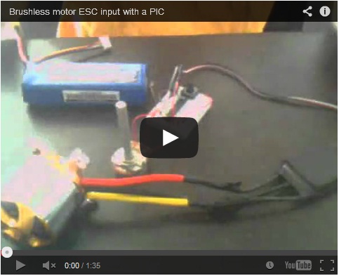
Simple background: this brushless motor was bought at Hobbyking for less than $20 and can put out something like 600W. Although that is pretty high, it is not to be used for wheeled vehicles, which have highly dynamic loads and high current spikes. These brushless motors are intended for R/C planes' propellers, which have very steady and predictable loads. I have it connected to an electronic speed controller (ESC), which I bought, that dishes out the current at the right times to the brushless motor based on a simple pulse-width modulated signal it receives. The ESC is necessary because brushless motors operate in a totally different way from DC motors. Brushless motors are 3-phase, and as a result have three wires that need to be connected to a power source. Where you could just apply a steady voltage to DC motor and the commutator takes care of current alternation, brushless motors require more deliberate control. This control is not the subject of this post. I use a PIC to easily create and control a PWM signal using PIC's onboard timers for the ESC to interpret. So this post is basically about programming PICs specifically, to generate a PWM signal, of any flavor or kind if you like.

The signal generated here is a standard servo signal of 50 Hz (period 20 ms) with a square wave pulse that ranges in width from 1 to 2 ms.

What the software does: The software uses PIC's Timer1 and Timer0 and interrupts to make the signal, whose length varies (of the signal that can vary from 1 to 2 ms, the 50 Hz cycle is fixed) based on an analog input from a potentiometer. The PIC is constantly polling and converting the signal from a potentiometer to a value from 0 to 255, while in the background the Timers are counting down. Timer1 has a fixed time length (of course defined by me) of 20 ms, and Timer0 has a length from 1 ms to 2 ms, determined by the ADC. Timer1 dictates when the pulse, whose length is determined by Timer0, occurs. Notice that every cycle there is at least a period of 18 ms where the signal is low. The timers counting down and the potentiometer signal polling occurs simultaneously. When the Timers countdown, interrupts stop the PIC from whatever it was doing, executes a specified procedure, and then the PIC resumes whatever it was doing. In this case, the interrupts would be used to stop and start signals.

The c code:
//Using default Internal Clock of 4 Mhz
//To use TMR1 at 50 Hz and 1:1 prescaler, set offset to 45535.
//TMR0 can vary from 7 to 132, or 2 ms to 1 ms, at 1:1 prescaler.
//Use TMR0 to control pulse width, even though TMR1 has much higher resolution, because TMR1 offset is 16 bits and may require lots of time to compute proper TMR1 offset from ADC value.

#include
__CONFIG(INTIO & WDTDIS & PWRTEN & MCLRDIS & UNPROTECT \
& UNPROTECT & BORDIS & IESODIS & FCMDIS);

unsigned int pulse = 0;

//Interrupt function
static void interrupt isr(void)
{
if(T0IF)
{
RC0 = 0;
}
if(TMR1IF)
{
TMR1IF = 0;
//Start 50 Hz cycle period.
TMR1L = 0b11011111;
TMR1H = 0b10110001;
//Turn on variable pulse.
RC0 = 1;
if(RC1 == 1) //safety switch (must be pressed).
{
TMR0 = pulse;
T0IF = 0;
}
else //off.
{
TMR0 = 132;
T0IF = 0;
}
}
}

void main(void)
{
//Setting ports.
TRISA = 0x00001001; // Set A0 (for ADC) and A3 (MCLR) to input, others output
PORTA = 0x00;
TRISC = 0b00000010; //Set C1 to input for safety on switch.
PORTC = 0x00;
//ADC configuration.
ADCON1 = 0x00;//So that ADC conversion clock is set to Fosc/2.
ADCON0 = 0b00000001;//ADC enabled.
ANSEL = 0x01; // Set A0 to analog, others digital

//Timer configuration
OPTION = 0b00000010; // Timer0 configuration, 1:8 prescaler.
TMR1L = 0b11011111;
TMR1H = 0b10110001;
T1CON = 0b00000001; // Timer1 configuration, including 1:1 Prescaler and TMR1ON = 1.

//Timer interrupt enabling.
T0IE = 1;
TMR1IE = 1; // Timer1 interrupt enable, needed with PEIE and GIE bits set.
PEIE = 1; // Peripheral interrupt enable, for Timer1.

//General interrupt enabling.
GIE = 1; // Global interrupt enable, for Timer1 and Timer0.

while(1)
{
GODONE=1; // initiate conversion.
while(GODONE) continue; // Wait for conversion to finish.
pulse = 7+ADRESH*125/255;
}
}

The c code is turned into a hex file via MPLAB and I program the microcontroller with the PICKit 2. The microcontroller is a PIC16F690. Analog-to-digital conversion signal (from potentiometer) input is at A0 and ouput PWM signal is at C0. There is an input at C1 for a momentary pushbutton, which needs to be held in order for an input at C1 to be high. This is for safety, as I want it to be easy to turn the motor off by just letting go of the pushbutton. So no matter how high a speed the potentiometer is set to, nothing will happen unless the pushbutton is held.

Since the ADC gives values from 0 to 255, the resolution, or how many speed levels, you have is limited to 256. So it does not matter whether you use Timer0 or Timer1 for determining the signal length (Timer1 has a much higher temporal resolution). I use Timer0 because it probably takes less time for the PIC to do the arithmetic of converting the ADC value to the appropriate number. Timer0 uses 8 bits to define counter number (up to 255 in decimal), while Timer1 uses 16 bits (up to 65535 in decimal)

Remember, when using PICs as standalone portable devices, two things should be done: there should be a capacitor across the power supply pins (here, .1 microFarad, and yes this is absolutely necessary, else the PIC just keeps turning off and on) and a resistor tying MCLR pin to the power supply (here 10 kOhm). Also, I tied the input C1 pin to ground, so that electrical noise wont make it go high and low unintentionally
 

reza_476

کاربران vip(افتخاری)
vip افتخاری
کاربر
2009-10-19
4,007
45,270
ایران
اسلام
براشلس موتور یعنی موتور بدون ذغال
اسپید کنترلر آن موتورها فقط برای کنترل دور موتور است ولی با آن بتنهایی راه اندازی نمیشوند بلکه آنها به یک گیرنده رادیو کنترل باید متصل شوند و با اهرم سمت چپ رادیو کنترل آن موتورها شروع به چرخش میکنند در اصل موتور هواپیما و هلیکوپترهای مدل هستند.


reza_476

کاربران vip(افتخاری)
vip افتخاری
کاربر
2009-10-19
4,007
45,270
ایران
پاسخ : عکسی از تشریح مدار موتور براشلس دو فاز

باسام
عکسی از تشریح مدار موتور براشلس دو فاز چون موتور دوسیمه است برای پرواز از سه فاز استفاده میشد

20101225140820434_06-b.jpg
 
آخرین ویرایش:
بالا