آی پی امداد
abtahi
آریا الکترونیک تکشو

استفاده از کامپیوتر به عنوان اسکوپ !!؟

IIII

کاربر
2013-03-07
128
276
سلام.

یکی از دوستان گفتن میشه از کامپیوتر به عنوان اسکوپ استفاده کرد

منم نرم افزار اسکوپ برای کامپیوتر رو نصب کردم . و کابل رابطش که یک نری فیش اسپیکر که به جای اسپیکر در پشت کامپیوتر وصل میشه. منفی
فیش رو به منفی ندار و یکی از سیم ها ( آخه 3 تا سیم هست ، یکی منفی و 2 تای دیگه برای وصل کردن به نقاط تست ) بین سیمی که میخوایم به نقاط در مدار بزنیم (طبق یه مقاله) باید یک مقاومت 33 کیلو و یه 470 کیلو سری کنیم بین سیم تا از ورود ولتاژ زیاد به کارت صدا جلوگیری کنه )

ولی من شک کردم که اگه سیم منفی رو به منفی مدار بزنیم مشکلی پیش نمیاد ؟؟

دوستان یک راهنمایی میکنین ؟؟

ممنون
 

jfrras

مدير انجمن تخصصی الکترونیک
مدیر تالار
2007-04-13
3,096
74,083
48
ایران
سلام.

یکی از دوستان گفتن میشه از کامپیوتر به عنوان اسکوپ استفاده کرد

منم نرم افزار اسکوپ برای کامپیوتر رو نصب کردم . و کابل رابطش که یک نری فیش اسپیکر که به جای اسپیکر در پشت کامپیوتر وصل میشه. منفی
فیش رو به منفی ندار و یکی از سیم ها ( آخه 3 تا سیم هست ، یکی منفی و 2 تای دیگه برای وصل کردن به نقاط تست ) بین سیمی که میخوایم به نقاط در مدار بزنیم (طبق یه مقاله) باید یک مقاومت 33 کیلو و یه 470 کیلو سری کنیم بین سیم تا از ورود ولتاژ زیاد به کارت صدا جلوگیری کنه )

ولی من شک کردم که اگه سیم منفی رو به منفی مدار بزنیم مشکلی پیش نمیاد ؟؟

دوستان یک راهنمایی میکنین ؟؟

ممنون


سلام
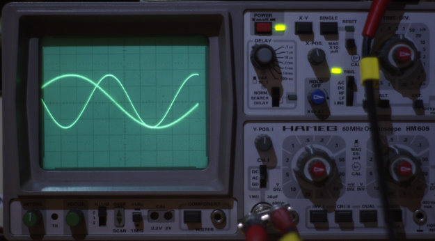
دوست عزیز میشه استفاده کرد ولی اینطور که شما توضیح دادید ممکنه به کارت صوت آسیب بزنه .

به این مطالب که همراه با نقشه است توجه کنید.


Front End Turns PC Sound Card into High-Speed Sampling Oscilloscope By Doug Mercer
Various software packages enable the stereo sound card found in a personal computer (PC) to provide oscilloscope-like displays, but the low-sample-rate, high-resolution analog-to-digital converters (ADCs) and ac-coupled front end are optimized for 20 kHz or less of usable bandwidth. This limited bandwidth can be extended—for repetitive waveforms—by using a sampling front end ahead of the sound card inputs. Subsampling the input waveform with a high-speed sample-and-hold amplifier (SHA)—followed by a low-pass filter to reconstruct and smooth the waveform—effectively stretches the time axis, allowing the PC to be used as a high-speed sampling oscilloscope. This article describes a front end and probe that provide an appropriate adaptation.
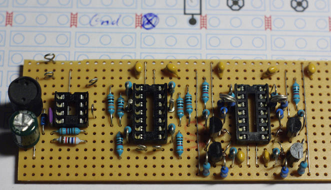
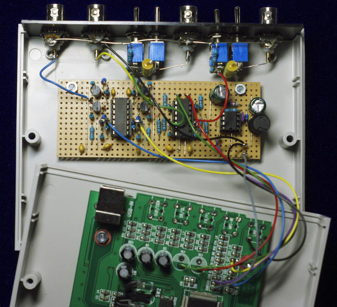
Figure 1 shows a schematic for a plug-in attachment that can be used for sampling with typical PC sound cards. It uses one AD783 high-speed sample-and-hold amplifier per oscilloscope channel. The sampling signal for the SHA is provided by the digital output of a clock-divider circuit; an example of one will be described. The AD783 input is buffered by a FET, so simple ac/dc input coupling can be used. In the two channels shown, 1-MΩ resistors (R1 and R3) provide dc bias when the dc-coupling jumper is open and the input is ac-coupled. The sampled output is low-pass filtered by the two-pole active RC networks shown. The filter need not be an active circuit, but the one shown usefully provides a buffered low impedance to drive the PC sound-card input.
AD45-11_BB_FIG_01.jpg
Figure 1. 2-channel analog sampling circuit.
The AD783 SHA provides a usable large-signal bandwidth up to a few megahertz. The effective slew rate at the input is above 100 V/µs. Input/output swing with a ±5-V supply is at least ±3 V. The small-signal 3-dB bandwidth for swings less than 500 mV p-p is close to 50 MHz.
With the front-end circuit of Figure 1, and a PC’s sound card employing the Visual Analyser[SUP]1[/SUP] software, the screen shot in Figure 2 illustrates a 2-MHz, single-cycle sine repeated at 1 MHz. The sampling clock provides 250-ns-wide sample pulses at an 80.321-kHz sample rate. The effective horizontal time base here is 333 ns/division. The PC sound card used in these examples uses an Analog Devices SoundMax[SUP]®[/SUP] codec sampling at 96 kSPS. In this example, the effective sampling rate is about 40 MSPS.
AD45-11_BB_FIG_02.jpg
Figure 2. 2-MHz single-cycle sine pulse at 1-MHz repetition rate.
Another screen shot was taken of a Gaussian sine pulse with a 1-MHz repetition rate (Figure 3). The sampling clock rate was again 80.321 kHz, with 250-ns sample pulse width.
AD45-11_BB_FIG_03.jpg
Figure 3. 4-MHz Gaussian sine pulse at 1-MHz repetition rate.
Example of a Sampling Clock Generator
The AD783 requires a narrow positive sampling pulse with a width between 150 ns and 250 ns. The sampling pulse must be very stable with low jitter in order for the displayed waveform to be stable without jumping back and forth. This requirement tends to limit possible clock choices to crystal-based oscillators. Another requirement is that the sampling rate be adjustable or tunable over a range from slightly less than 100 kHz to about 500 kHz. The tuning steps between sampling frequencies need to be relatively fine for downsampled signals to fall somewhere within the 20 Hz to 20 kHz audio bandwidth of the sound card. A divide-by-N circuit, such as that shown in Figure 4, and a crystal oscillator with a frequency between 10 MHz and 20 MHz (IC4), can provide up to 200 or more different sample rates from 80 kHz to 350 kHz, with step sizes from 300 Hz to 5 kHz. In this example, using two 74HC191 4-bit binary up/down counters, N can be any integer between 4 and 256. Alternatively, decade counters, such as the 74HC190, with identical pinouts to the 74HC191, could be used to provide a range of N from 4 to 100. The division ratio is set using the two hex switches, S1 and S2. Switch S3 sets the counters to count up or count down. Resistor R1 (250 Ω) and Capacitor C1 (68 pF) add a slight delay to the terminal count output before it asynchronously loads the start-count values. The four NAND gates of the 74HC00 are used to implement a one shot that makes a 200 ns sample pulse when R12 is 2.7 kΩ and C2 is 68 pF.
AD45-11_BB_FIG_04.jpg
Figure 4. Sampling clock divider circuit.
IC4 is a fixed-frequency metal-can crystal oscillator. Another approach would be to use CMOS inverters (74HC04) and a discrete crystal, X1, to form an oscillator, as shown in Figure 5. This approach, while using more components than the all-in-one metal-can oscillator, permits a small amount of frequency tuning by adjusting Capacitor C1 to pull the crystal frequency.
AD45-11_BB_FIG_05.jpg
Figure 5. Discrete crystal oscillator with mechanical tuning.
To avoid the mechanically variable component, use a varactor diode—which has voltage-dependent capacitance—for D1, as shown in Figure 6.
AD45-11_BB_FIG_06.jpg
Figure 6. Discrete crystal oscillator with voltage tuning.
Examples of Active Reconstruction Filters
Figure 7 and Figure 8 show active filter designs that should work well in place of a simple passive RC filter. Figure 7 shows a second-order Sallen-Key filter, with a corner frequency of about 39 kHz, using standard resistance and capacitance values. The AD8042 and AD822 dual op amps, specified for low supply voltage and wide swing, are good choices. The filter has a gain of +1 in the pass band.
AD45-11_BB_FIG_07.jpg
Figure 7. Sallen-Key 39-kHz low-pass filter.
Figure 8 shows another second-order multiple-feedback (MFB) filter with a corner frequency of about 33 kHz, using standard resistance and capacitance values. This filter has a pass-band gain of –1, so—if it is used—select the invert button on the scope software in order for the displayed waveform to be right-side up.
AD45-11_BB_FIG_08.jpg
Figure 8. MFB 33-kHz low-pass filter.
Powering the Circuits
The AD783 and the amplifier used in the reconstruction filter require dual power supplies. These could be provided simply by six AA batteries, with three providing +4.5 V and the other three providing –4.5 V. Or, a single 9-V battery could be used, with a resistance divider providing a midsupply voltage as the ground—which would need to be buffered by an op amp to supply any ground currents required by the circuit; alternatively, an adjustable linear regulator could be used to produce a voltage of approximately 4.5 V with respect to the negative battery terminal for use as the ground reference.
Yet another option would be to use the +5 V provided by a spare PC or laptop USB port. The –5 V could be generated by a dc-to-dc voltage inverter, such as the Analog Devices ADM8829—in a surface-mount package—or the ICL7660 in a DIP from Intersil. Special care will be required to avoid interference from switching noise generated by the dc-to-dc voltage inverter.
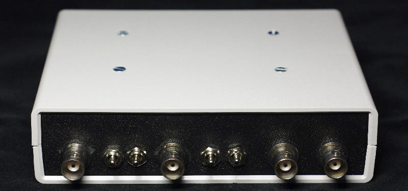
Input Attenuators
The small-signal gain of the AD783 is much higher than its full swing bandwidth. By inserting a 10:1 resistive attenuator ahead of the sampler to limit the maximum signal swing, usable bandwidth well beyond 20 MHz is possible. Relatively low cost scope probes are available from companies such as Syscomp Electronic Design, Ltd.[SUP]2[/SUP] (Figure 9). At this writing:

  • Oscilloscope probes (P6040) with 40-MHz bandwidth, 1×/10×switchable, cost $29.99 per pair from Syscomp Electronic Design.
AD45-11_BB_FIG_09.jpg
Figure 9. P6040 1×/10× scope probes.
  • HobbyLab[SUP]3[/SUP] sells the 20-MHz 10:1 version oscilloscope probes (GT-P6020) for $19.50 per pair.
  • Gabotronics.com[SUP]4[/SUP] sells both 100-MHz P2100 and 60-MHz P2060 generic probes for about $10.00 each.
Using the Probes
The P2100 100-MHz 10× probes, used to take the Soundcard[SUP]5[/SUP] screen shots in Figure 10, Figure 11, and Figure 12, can compensate for input capacitance in the range from 10 pF to 35 pF. This seems to be a sufficient adjustment range for the proposed circuit if the PC board wire lengths are kept as short as possible. With the 10× probe, the input looks like 10 MΩ and 18 pF and can support input voltages up to ±30 V.
To demonstrate the AD783 sample-and-hold input stage, the probe compensation was first adjusted using a 1-kHz flat-top square wave. The screen shots show the response for various signals with frequencies of 1 MHz and 50 MHz. The two screen shots in Figure 10 show one channel with a 1 MHz, 5-V p-p square wave (a), and a 50-MHz, 5-V p-p square wave (b). In each case, the sample clock was adjusted for a downsampled signal frequency of about 500 Hz, so that any sound-card response differences were eliminated. Thus, the effective time scale is 500 ns/division for the screen shot on the left and 10 ns/division for the screen shot on the right. The sound card input gain was set for the scope software to report a 1.072-V p-p amplitude for the 1-MHz input and a 762.2-mV p-p amplitude for the 50-MHz input. The ratio of 0.7622/1.072 is close to –3 dB. This measurement shows that the combination of the 100-MHz 10× probe and the AD783 has a 50-MHz, 3-dB bandwidth.
AD45-11_BB_FIG_10.jpg
(a)(b)
Figure 10. Single channel 10× probe 1 MHz (a) and 50 MHz (b) 5-V p-p input square waves.
In Figure 11, the same 1-MHz (a) and 50-MHz signals (b) are applied to both channels. From these two overlaid screen shots of both channels, one can see that there is good gain-, offset-, and delay-matching between the two channels.
AD45-11_BB_FIG_11.jpg
(a)(b)
Figure 11. Dual-trace 2-channel matching, 10× probes, 1-MHz (a) and 50-MHz (b) 5-V p-p input square waves.
The final screen shot (Figure 12) is of a 375-kHz, 5-V p-p square wave (red trace) and a 1.5-MHz 42 ns wide 5-V p-p pulse (green trace). The horizontal scale is 333 ns/division. The AD783 sampler maintains the full 5-V swing, even for these narrow 42-ns wide pulses.
[hide]
AD45-11_BB_FIG_12.jpg

[/hide]
Figure 12. Dual-trace 2-channel, 10× probes, 375-kHz, 5-V p-p square wave and 1.5-MHz, 42-ns 5-V p-p pulse.
References
[SUP]1[/SUP]Visual Analyser is a complete professional real-time software package that transforms a PC into a complete set of measurement instruments. No new hardware is necessary as it uses the PC’s sound card. http://www.sillanumsoft.org/.
[SUP]2[/SUP]Syscomp Electronic Design, Ltd. http://www.syscompdesign.com/Accessories.html.
[SUP]3[/SUP]HobbyLab http://securedwithssl.com/HobbyLab-us/product/63258ffa-dcc8-4508-8152-d2461d943169.aspx.
[SUP]4[/SUP]Gabotronics http://www.gabotronics.com/accesories-and-cables/view-all-products.htm.
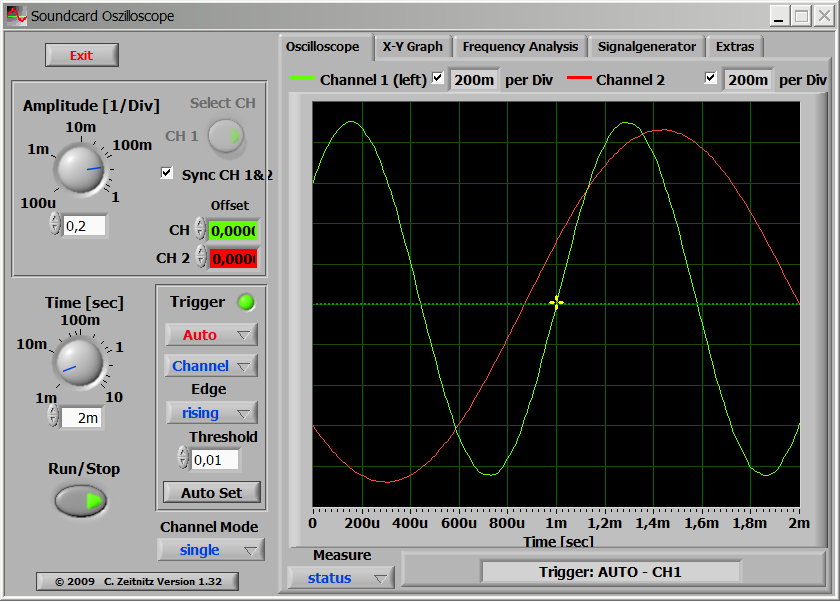
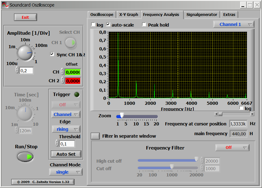
[SUP]5[/SUP]The PC-based Soundcard oscilloscope receives its data from the sound card with 44.1-kHz sampling rate and 16-bit resolution. Also available is WaveIO, a Soundcard Interface for LabView software. http://www.zeitnitz.de/Christian/scope_en.
Author
 

jfrras

مدير انجمن تخصصی الکترونیک
مدیر تالار
2007-04-13
3,096
74,083
48
ایران
قسمت دوم:


[h=1]A new soundcard oscilloscope[/h]

A couple of years ago I presented a preamplifier on my homepage which allowed it to use standard oscilloscope probes on the line input of a soundcard. This small circuit solved the problem that a soundcard has quite a low impedance on its line inputs which makes it unusable for measuring high-impedance signals.
Already at that time I found quite a few application programs to use the soundcard as a simple and cheap storage oscilloscope, but nobody seemed to bother about the impedance issue or any way to connect oscilloscope probes to a soundcard.
My previous design used a single-supply operational amplifier and a 9 V battery to offer a standardized input impedance of 1 MΩ at the input and buffer the input signal which is then capacitively coupled into the line input of a soundcard. A directly coupled signal would have required a surgical procedure on the soundcard itself, which I deemed too risky.
Now, you can buy external USB soundcards for cheap money and about a year ago I got the idea to modify such a card for a DC connection of the input signal. In 2008 also the electronics journal Elektor took again up the idea of using the soundcard for electronic measurements. So now I finally went all the way and designed a universal input/output circuitry which can be adapted to different soundcards and offers two input channels with a standardized input impedance of 1 MΩ and two low-impedance, DC connected output channels which can drive an amplitude of 1 V into a 40 Ω load.
[h=4]The USB soundcard[/h] My design is based on the USB soundcard SC-5500P from Trust which is based on the CMedia USB sound chip CM106. From the datasheet of this chip you can see that it uses a single +5 V supply voltage and handles negative amplitudes of sound signals by offsetting these with a reference voltage of +2.25 V which is available on pin 38 of the QFP100-package for the connection of external bypass capacitors.
In order to connect a signal to the inputs of this chip without coupling capacitors you have to add this reference voltage to the signal, when taking the output signal you would have to subtract this voltage from the signal – this can easily be done with operational amplifiers.
The 5.1 soundcard comes with 2 stereo output channels, 1 mono output channel, 1 stereo line-in channel and 1 mono microphone input channel (the chip itself actually supports stereo microphone input, but this is not externally available).
[h=4]Supply voltage[/h] Since the soundcard itself is powered from USB, a single +5 V supply voltage is available on the card. Also the current which can be drawn from this supply is limited, but since I am only adding a handful of operational amplifiers and limit the output current from the signal output this is not a problem.
In order to work with directly coupled positive and negative signals, a negative supply voltage is needed. I chose to create this supply voltage with a small DC/DC converter based on the MC34063 chip.
A first also showed that it was necessary to buffer the reference voltage from the sound chip itself, because the sound chip was not able to drive the four inputs where I needed the reference voltage (one for each input channel and one for each output channel). Therefore I had to add a voltage follower based on a single operational amplifier.
So here is the schematic diagram for the supply part:

(The gray components are original parts on the sound card.)
[h=4]The input circuit[/h] The input circuit consists of a voltage follower with an input impedance of 1 MΩ followed by a voltage adder which takes the 2.25 V reference voltage from the soundcard and adds it to the input signal. This way a symmetric sine wave with an amplitude of 1 V would be transformed into a sine wave swinging between 1.25 V and 3.25 V which is then fed into the sound chips analog-to-digital converter inputs. All the conversion for both channels is performed in a single quad operational amplifier package. I chose the TL074, but for this application the exact type of operational amplifier is not critical. The total amplification of the two stages is 1 – i.e. the input signal is presented to the sound chip with unchanged amplitude. At the very input you can easily implement an attenuator as found on conventional oscilloscopes, allowing you to take only 1/10 or any other fraction of the input signal – I realized a selectable 1/10 attenuation in this circuit.
In order to connect it to the soundcard with no interference with the original input circuitry I removed the coupling capacitors (C22 and C27, SMD 3 μF) and soldered the connection cable to one of the solder pads of these capacitors.
Here is the schematic diagram for the input circuit:

[h=4]The output circuit[/h] Apart from an oscilloscope a signal generator is also a very important tool in an electronics workshop. And some soundcard oscilloscope software also provides means to send output signals to the soundcard, emulating a signal generator. Again the original output circuit of a soundcard might not be up to the task and especially its specifications are almost certainly unknown.
I therefore even designed an output stage. It also consists of two operational amplifiers per channel – one to subtract the 2.25 V reference voltage from the sound chips output signal, and the second one to drive a complementary pair of bipolar transistors. This is not a real power amplifier and the signal amplitude is limited to the actual output voltage of the sound chip, since the two operational amplifier stages have an amplification of 1. But it is able to drive a signal with a 1 V amplitude into a standard 50 Ω load with low distortion.
In order to connect it to the soundcard, I removed the original coupling capacitors (C10 and C12, 470 μF through-hole) and attached wires to one of these capacitors pads on the circuit board.
Here is the schematic diagram for the output circuit:

[h=4]Putting it all together[/h] I built up the circuit on a piece of stripboard small enough to fit into a box together with the circuit board of the soundcard. In order to optimize the design I first drew the layout in XCircuit and then soldered it together starting with the wire bridges. The layout on the stripboard looks like this:
[hide] [/hide]


Assembling the circuit on the stripboard according to the printed design.


Soldering the connection wires to the corresponding pads on the soundcard.


Connecting the amplifier board with the soundcard inside the box. You can notice the still absent voltage follower for the reference voltage on the stripboard - I added it after a failed first test.


440 Hz sine wave from the soundcard and 880 Hz sine wave from a signal generator on a Hameg 60 MHz analog oscilloscope.


The same two signals as above, 440 Hz sine wave from the soundcard and 880 Hz sine wave from a signal generator, seen on the computer screen.

[h=4]Software[/h] There seem to be several applications around on the internet, which can use the soundcard as an oscilloscope. Earlier I was advertising a program called audioTester from http://www.audiotester.de/ on my homepage. It also has seen an upgrade in the recent years, but I haven’t tested it again, yet.
Recently I found another program from Germany, Soundcard Oscilloscope from http://www.zeitnitz.de/. This program allows to control the soundcard output as quite a versatile signal generator, including a noise source, frequency sweep and adjustable phase delay between the two channels. It offers a two channel scope display with cursors and various trigger settings, an independent X-Y display and a spectrum analyzer. It also allows to highpass/lowpass/bandpass/notch filter the input signal and display the result on the scope screen.
The Soundcard Oscilloscope software is free for private and educational use, but I chose to register my copy of the software and plan to contact the author soon with some additional suggestions, but also some flaws which I think I have discovered.

Spectrum display of a 440 Hz square wave signal fed back from the soundcard output through the amplifier card into the input.

[h=4]Cost[/h]
partsupplierprice/piecesum
USB sound cardKjell & Co.SEK 299SEK 299
plastic boxKjell & Co.SEK 69SEK 69
stripboardKjell & Co.SEK 45SEK 45
TL074Electrokit.seSEK 10SEK 20
TL071Electrokit.seSEK 6SEK 6
MC34063Electrokit.seSEK 15SEK 15
BNC socketElectrokit.seSEK 8SEK 32
switchElectrokit.seSEK 6SEK 24
capacitors, resistors, diodes, transistorsown stockSEK 50SEK 50


jfrras

مدير انجمن تخصصی الکترونیک
مدیر تالار
2007-04-13
3,096
74,083
48
ایران
قسمت سوم:

[SIZE=+2]Sound card based multimeter[/SIZE]
Updated Dec 25, 2008; program updated Dec 28, 2008.

[h=4]Contents[/h] [SIZE=-1]

[/SIZE]
[h=4]Preface[/h] [SIZE=-1] PC sound card, standard component of practically all current personal computers, consists, in minimum, of two parts: [/SIZE]

  • [SIZE=-1]
  • mixer
  • A/D converter [/SIZE]
[SIZE=-1] Those parts are usually doubled as all sound cards are two channels - e. g. stereo devices. They may contain other parts, but from the point of view of analog to digital (A/D) signal processing they may not be as important.
Mixer is device joining analog signals from different signal sources into one which is delivered to A/D conversion. Important feature of current mixers is full software control of gain and level of all channels.
A/D converter is usually high precision 16-bit analog to digital converter with maximum sampling rate 44.1 kHz, or 48 kHz.
All (4 ;-) sound cards we've tested and analyzed have the same feature - all their line-in inputs (and others too) are insulated from DC input by condenser. The reason is, clearly, to set zero level of processed sound signal stable and close to zero. This is, however, a strong limitation for other use, for example for DC measurements.
The situation, fortunately, is not so bad as it seems...

[h=4]Results of SB analysis[/h] [SIZE=-1] We've analyzed, with a good magnifying glass and ohmmeter, LINE IN inputs of four different sound cards - three from Creative Labs, one from Manli: [/SIZE]

  • [SIZE=-1]
  • SB16 (PCI), model CT4810(?),
  • AWE-64 (IDE), model 4520,
  • Audio PCI 5000 (PCI), with chip ES1371,
  • Manli CMI8738SX (PCI) [/SIZE]
[SIZE=-1] Inputs of SB16, Audio PCI5000, AWE-64 and CMI8738SX, respectively, are on the Fig. 1.
4.gif

Fig. 1: SB16, Audio PCI5000, AWE-64 and CMI8738SX LINE IN inputs.
As it can be seen, three inputs are very simple. Input of AWE-64 is a bit more complicated. It contains standard FET operating amplifier, but not condenser at the input. The condenser is at the output, however...
All four sound cards have DC default level at mixer input significantly high. The values displayed don't reflect reality. It was found, that it is close to 2.5V. Direct connection of external DC is not applicable. Is there a solution?

[h=4]Possibility of DC input solution[/h] There exists well known application of operating amplifier - differential amplifier. It's schematics (Fig. 2) is quite simple.
5.gif

Fig. 2: Differential amplifier.
The output is joined with inputs by the formula:
6.gif

The analysis of the formula shows, that at the output there can be defined DC level even in the case that U[SUB]2[/SUB] will be zero - provided appropriate signal will be delivered as U[SUB]1[/SUB].
A brief inspection of Fig. 1 shows, that AWE-64 already has operational amplifier. Good new! It is candidate No. 1. Assumed changes will be negligible.

[h=4]Result[/h] What is needed:


  • disconnect noninverting input from ground,
  • make tunable source of U[SUB]1[/SUB], one for both channels should be enough,
  • with a piece of wire make a shortage between condenser pins,
  • with running PC tune U[SUB]1[/SUB] to get appropriate DC level.
To make small board with operating amplifier and a few other components is possible too. It is only solution for the rest three sound cards (and the majority of others). The resulting schematic is on Fig. 3.
7.gif

Fig. 3: AWE-64 input modification.
It works fine. With the device we did a few measurements. It was found that the maximum sensitivity is approximately +/- 100 mV. Based on +/- 5 V power it can be assumed that maximum input DC signal will be approximately +/- 2.5 V. Higher voltages must be decreased by hardware divider.
With operational amplifier on small PCB we checked SB16 and CMI8738SX too. The final version had been made with CMI8738SX Manli sound card. Only reason for selection was that it was cheapest and is currently available. Additional to Fig. 3 the schematics contais -5V chip, as sound card has none.
The rest are a bit older models. The results of all sound cards were comparable.
The solution is not limited to AWE-64 and comparables. It seems any sound card can be modified provided small PCB with operational amplifier will be added. At the begining AWE-64 was chosen only due to fact it already has the (pre)amplifier. However for the final solution it was not suitable - in between mother board of home computer changed and ISA slot gone...

[h=4]The final solution[/h] To test, and even to use the device, one need some useful program. As a first choice we decided to get Konstantin Zeldovich's Winscope. It is complete, sophisticated and ... free. However, its use for more serious job is not very easy as it doesn't contain calibration feature and, what's most important, it doesn't allow AC/DC V/A measurements with numeric output.
To meet our needs we developed original program. It is two channel:

  • oscilloscope,
  • AC/DC V/A meter,
  • frequency meter,
  • VU-meter
with possibility to save data in the form of regular WAV file or as a CSV (comma separated variables) data file, which is easily analyzable with majority of current spreadsheet programs. Hardware
To make it a real multimeter we equipped the device with manual range switch. Its construction is very simple:
8.gif

Fig. 4: Manual range switch (one channel only).
The resistors used are standard ones, e. g. no special selection is needed - calibration will ensure the final accuracy. Resistor 1M is standard 0.25 W resistor, resistor 11M is old 0.5W one from stock. It may be difficult nowadays, far from vacuum tubes era, to get one. But who has stock... Anyway, it can be any in the range 5 - 15M, serial combination of smaller resistors too... Resistor 0.1Ohm is a small piece of some resistive wire of unknown origin (maybe from car power controller?) from the same stock.
No special components were used. Dual switch was constructed in small metal box with input bushings. It is connected with LINE IN input by standard shielded stereo cable. Switch takes very little space at the table, PC sits near the table, so no change in the organization in the room was needed.
Software
It was created program to use all information available. It is quite complex one. As it can be seen from Fig. 5, it is dual beam oscilloscope-like device combined with AC/DC multimeter and frequency meter.
9.gif

Fig. 5: Soundscope main screen.

Soundscope screen has the following parts:
  1. scope window
  2. channel controls panel
  3. multimeter & controls panel
The scope window has:

  • width 11.6 ms or 92.9 ms depending on sweep range selection (see below),
  • height +/- 3 depending on range switch selection (see below),
Single click on scope window activates image save dialog - it allows to save screen shots. Currently supported are BMP, GIF and JPG formats.
Below the scope window there is status bar displaying (sometimes) status messages.
Panel of channel controls on the right side of the scope window contains 2 identical sets of controls for each channel - A and B - (from left to right):

  • zero level
  • gain
  • trigger level (below gain control)
All three controls influence only scope display. Calibration assumes gain set at maximum level. Multimeter & controls panel contains (from top to bottom):

  • multimeters
  • sound device selector
  • trigger control
  • time base control
  • operation controlls
Multimeter window contains two displays - larger and smaller ones - larger one displays voltage/current or raw data depending of calibration/raw data button status. Smaller one displays frequency in Hz.
At the right side there are range switch buttons. They are active only if soundscope is calibrated.
AC measurement is enabled by "Hz" button. When pressed, both windows - multimeter and frequency - display AC values.
Below those multimeters there is sound device selector.
The trigger control group consists of (from top to bottom):

  • triggering enable/disable
  • channel A or B selection
  • indicator of active triggering (yellow=active)
Time base control contains 2 butons in group:

  • fast - 1 ms/div
  • slow - 10 ms/div
Data saving definition button opens small window for data saving options:
10.gif

Fig. 6: Data saving definition screen.
It can be selected continual saving into regular WAV file format or timed sample data saving into special text file (CSV). Sampling period, capturing time and data file name can be set.
Right lower corner contains by control buttons:

  • calibrated/raw display button
  • start/stop button
  • hold/release button
  • start/stop data saving button
  • about
  • help
  • program close
Description
Program was created using Borland Delphi 6. No shareware or commercial libraries or components were used. To control mixer it was used excellent free mixer component developed by Vit Kovalcik. To display numeric values nice it was into Microsoft Windows installed LED display font - NI7SEG.TTF found somewhere on the Internet.
All copyrights of the program are owned by the authors. The noncomercial use of the program is free of any charge. All other use must be consulted with the authors.
Program runs under Microsoft Windows 2000, XP and 98. It successfuly runs at AMD K6-2 333MHz/64MB RAM. It may have problems on slower old machines.
Program is based on LINE IN inputs use. It is set to use two-channel 16-bit A/D conversion at 44.1 kHz sampling frequency.
Buffer size of the input sampling is 4096 samples, e. g. measurement frequency is 10.7 measurement per second.
Due to low sound card sampling frequency the highest frequency of the acceptable processed signal is around 10kHz. Higher frequencies are processed too, but the AC accuracy drops down.
Anyway DC measurements can be quite accurate, depending on calibration accuracy, of course and sound device A/D converter quuality.
The main domain of the device use should be, except of use as standard multimeter, DC and low frequency AC measurements.
AC amplitude measurements are achieved by software rectifying - the value displayed is close to effective value of the AC signal.
Frequency measurement is achieved by periods count measurement. As the measurement is sampled by 1/44 100 s, it is also measure of the frequency display accuracy. The smallest measurable frequency is around 20Hz.
Triggering is derived from channel A or B. There is no possibility to have triggered both channels. Triggering level can be set. Trigger level is not dependent on display zero level. Currently only positive levels can be set.
As the signal is sampled, e. g. not continual, the resulting triggered display is usually not fully stable.
Successful use of the program expects proper sound card setup. It is accessible via MS Windows Control panel -> Sounds and Multimedia -> Audio -> Recording setup. For more details check Microsoft Windows help.
5.png

An example of sound recording setup parameters.
As personal computers can have more than one sound card, proper card selection and setup is prerequisite.
Hardware modification described in this article, provided properly set, does not influence sound card standard features in any way. The modified card can be still used the standard way.
Calibration
Since the soundscope can be used as no calibrated, it's not its goal. To use multimeter functions it is necessary to calibrate all ranges.
Before calibration is started, it is suggested to measure linearity and sensitivity of the LINE IN input. It can be easily done using voltage calibration circuit described below.
To calibrate soundscope properly it is needed to prepare:

  • variable voltage/current source 1 to 15V DC/1A,
  • good potentiometer,
  • good multimeter, preferably digital one,
  • manual range switch properly set and connected with LINE IN input of sound card.
Calibration is three steps process. It consists zero level calibration, sensitivity measurement and measurement ranges calibration, which consists of three identical steps to calibrate voltage ranges and one step to calibrate current range (if used).
First step is zero level calibration. It requires disconnect any external voltages from inputs and connecting both ones with ground. Soundscope is switched to Raw data mode. Average value is read for each channel and written into program INI file.
Second step is sensitivity calibration. It requires connecting potentiometer with external DC voltage to both inputs. Soundscope is switched to "Raw data" mode. Potentiometer is set to minimum and slowly turning to get signal as close as possible to red line above (or belove) zero line. Voltage required and average raw value is read for each channel and written into program INI file. There is only one value for both channels. They should not differ in sensitivity, however.
To calibrate voltage ranges one is expected to use circuit according Fig.7. Use of regulated power source is very convenient, anyway the calibration can be sufficiently done using batteries as power source. In this case small lamp should be used to limit current.

Current range is calibrated with the help of circuit on Fig. 8. It should be noted, that ground bushing is not used. This is possible only if the power source has ground insulated from common ground. If it is not available, battery with lamp should be used.
11.gif

Fig. 7: Voltage calibration circuit.
12.gif

Fig. 8: Current calibration circuit.

Calibration process expects to switch Soundscope to Calibrated mode and have all CalFactorR, CalFactorL values in INI file sections [Range1].. [Range4] set to "1". Calibration process contains following steps:

  1. select measurement range on range selector (the same in both channels)
  2. set corresponding range on manual range switch
  3. bring externam voltage/current to inputs
  4. set voltage/current level to be exactly identical with range switch value
  5. read voltage/current values displayed on both displays
  6. calculate CalFactorR, CalFactorL values and write them to INI file
    Example:
    DC input: 0.2V
    Display A: 0.192V
    Display B: 0.211V

    CalFactorR = 0.2/0.192 = 1.0416666667
    CalFactorL = 0.2/0.211 = 0,9478672986
Program INI file
Program doesn't write anything to the MS Windows registry anymore. All required information is now stored in the INI file. It is standard ASCII text file. To change values in the INI file it is expected to use ASCII editor, Windows Notepad is good enough. Use of Winword may produce non-ASCII file and program will crash.
Program INI file name is soundscope.ini and it resides in the same directory as program file. It has following structure:

[SIZE=-1][Program][/SIZE][SIZE=-1] [/SIZE]
[SIZE=-1]Debug = 0[/SIZE][SIZE=-1]If set to "1" it activates program log creation[/SIZE]
[SIZE=-1]XPlook = 0[/SIZE][SIZE=-1]for "classical" Windows theme use "0", for parrot-like XP theme use "1"[/SIZE]
[SIZE=-1][Devices][/SIZE][SIZE=-1] [/SIZE]
[SIZE=-1]Device Name = C-Media USB Headphone Set[/SIZE][SIZE=-1]Selection of sound device to use, if not found, first one available will be used instead.[/SIZE]
[SIZE=-1]LineIn Name = Microphone[/SIZE][SIZE=-1]Exact name of input channel to use. Can be found in Control panel - Sounds and Audio Devices settings. It is very important to set correctly, othervise program will not work [/SIZE]
[SIZE=-1][Calibration][/SIZE][SIZE=-1] [/SIZE]
[SIZE=-1]Zero left = 0
Zero right = 0 [/SIZE]
[SIZE=-1]Raw average values of each channel[/SIZE]
[SIZE=-1]MaxLevel = 12480[/SIZE][SIZE=-1] [/SIZE]
[SIZE=-1]MaxVoltage = 0,117[/SIZE][SIZE=-1] [/SIZE]
[SIZE=-1][Range1]..[Range4][/SIZE][SIZE=-1] [/SIZE]
[SIZE=-1]LabelL = 0.2V,
LabelR = 0.2V [/SIZE]
[SIZE=-1]Range for channel A and B respectively. It is both label for range switch and internal calculations parameter.[/SIZE]
[SIZE=-1]CalFactorR = 1
CalFactorL = 1[/SIZE]
[SIZE=-1]Correction callibration factors. Before calibration is dome it is "1", after calibration it changes. Never set "0", othervise program will crash.[/SIZE]
[SIZE=-1][Capture][/SIZE][SIZE=-1]This section contains parameters written by program alone. Don't change any of them.[/SIZE]
[SIZE=-1]NameOfFile =captured.csv[/SIZE][SIZE=-1] [/SIZE]
[SIZE=-1]SamplingType = CSV[/SIZE][SIZE=-1] [/SIZE]
[SIZE=-1]CaptureTime =60[/SIZE][SIZE=-1] [/SIZE]
[SIZE=-1]SamplingPeriod =1[/SIZE][SIZE=-1] [/SIZE]
[SIZE=-1]TimeMeasure = min[/SIZE][SIZE=-1] [/SIZE]
[SIZE=-1][Visible][/SIZE][SIZE=-1]This section contains labels used for display. Translation to other language will translate user interface.[/SIZE]

[h=4]Notes for construction[/h] There are no special components used, except 11M resistor in switch. However silicon diodes at the input should be fast ones and should have very high resistivity. 1k resistor conducting signal to them and LINE IN should be as small as possible - its function is to be fuse. It should burn to prevent the input from overloading. Diodes should bear the "burning" current, of course. For soldering at the sound card microsolder is needed. Transformer solder must be avoided. A good lens or glasses and a certainty in hand may be needed too...
Be careful when disconnecting input pins from ground (provided sound card has preamplifier already). SMD chips are quite fragile!
We glued small piece of universal PCB carrying additional components close to the LINE IN input. All joins we did with insulated thin copper wires.
The overall view of the experimental prototype can be seen on Fig. 9.
[/SIZE][SIZE=-1]
20.jpg

Fig. 9: Prototype view.

[h=4]Features summary[/h]
[SIZE=-1]sampling frequency[/SIZE][SIZE=-1]44.100 Hz[/SIZE]
[SIZE=-1]measuring frequency[/SIZE][SIZE=-1]approx. 10.7/s[/SIZE]
[SIZE=-1]measuring ranges[/SIZE][SIZE=-1]0.3, 3, 30V
and 3A[/SIZE]
[SIZE=-1]accuracy[/SIZE][SIZE=-1]better than 1%[SUP]*)[/SUP][/SIZE]
[SIZE=-1]type of measurement[/SIZE][SIZE=-1]AC and DC[/SIZE]
[SIZE=-1]maximum input frequency[/SIZE][SIZE=-1]22kHz[/SIZE]
[SIZE=-1]working input frequency range[/SIZE][SIZE=-1]20Hz - 10kHz[/SIZE]
[SIZE=-1]input resistance on voltage ranges[/SIZE][SIZE=-1]333kOhm/V
(100k, 1.1M, 12.1M)[/SIZE]
[SIZE=-1]input resistance on current range[/SIZE][SIZE=-1]0.1Ohm[/SIZE]
[SIZE=-1]data saving file format[/SIZE][SIZE=-1]WAV or CSV[/SIZE]
[SIZE=-1]sampling times[/SIZE][SIZE=-1]continual,
1/4, 1/2, 1, 15s,
1, 5, 15, 60min[/SIZE]
[SIZE=-1]saving time range[/SIZE][SIZE=-1]1s - 9999min[SUP]**)[/SUP][/SIZE]
[/SIZE][/SIZE]
 

IIII

کاربر
2013-03-07
128
276
استاد ممنون. من اسکوپ را برای تست فرکانس و پالس فلزیاب میخواستم. خواستم بدونم باید قطعه ی رابطی بین مدار و کامپیوتر قرار بدهیم ؟؟

ممنون
 

parse gade

کاربر
2010-09-26
326
556
دوست خوبمون اقا jfrras زحمت کشیدن و این مدارات رو اینجا قرار دادند.ولی با استفاده از تقسیم مقاومت و یه فیش استریو هم میشه اسکوپ ساخت.من الان دوساله که دارم به طور مداوم استفاده میکنم.اینو هم بگم که دقت این مدارات تا 25کیلوهرتز
 

gadraj

معاون مدیر کل
معاونت انجمن
2007-05-09
5,023
106,550
سلام.

یکی از دوستان گفتن میشه از کامپیوتر به عنوان اسکوپ استفاده کرد

منم نرم افزار اسکوپ برای کامپیوتر رو نصب کردم . و کابل رابطش که یک نری فیش اسپیکر که به جای اسپیکر در پشت کامپیوتر وصل میشه. منفی
فیش رو به منفی ندار و یکی از سیم ها ( آخه 3 تا سیم هست ، یکی منفی و 2 تای دیگه برای وصل کردن به نقاط تست ) بین سیمی که میخوایم به نقاط در مدار بزنیم (طبق یه مقاله) باید یک مقاومت 33 کیلو و یه 470 کیلو سری کنیم بین سیم تا از ورود ولتاژ زیاد به کارت صدا جلوگیری کنه )

ولی من شک کردم که اگه سیم منفی رو به منفی مدار بزنیم مشکلی پیش نمیاد ؟؟

دوستان یک راهنمایی میکنین ؟؟

ممنون

با سلام و با تشکر از دوست خوبمون اقای {
jfrras } که مدارات کاربردی را پیشنهاد کردند .
ببینید دوست عزیز این نرم افزار که بیان کردین با استفاده از کارت صوتی موجود روی مادر برد و تا فرکانسهای زیر 16 کیلوهرتز و دامنه سیگنال وارده محدود شده !! جواب خواهد داد و نباید ازش انتظار یک اسکوپ استاندارد چند میلیونی را داشته باشید .
دوم اینکه : [hide] [/hide][hide][/hide]
[hide]توجه توجه !!! باید از ورودی AUX یا لاین صوتی استفاده کنید نه از خروجی اسپیکر !!!!{ شما از اسپیکر نوشتین } کاریست بس اشتباه و استفاده در این صورت به کارت صوتی مادر برد لطمه خواهد زد . [/hide]
نرم افزار فوق با دریافت سیگنال از ورودی کارت صوتی انرا به شکل موجهایی تبدیل میکند که در نمایشگر قابل نمایش و انالیز خواهد بود و هیچ واسطه دیگری هم نیاز ندارد .
موفق باشید .


gadraj

معاون مدیر کل
معاونت انجمن
2007-05-09
5,023
106,550
با سلام ببخشید این نرم افزار را از کجا باید تهیه کرد
با سلام :
نرم افزار فوق در بخش اموزش گام به گام با عنوان تبدیل کامپیوتر به اسیلوسکوپ و نوعی مجهز تر با عنوان {هر انچه ابزاری که یک الکترونیک کار نیاز دارد } در بخش نرم افزار همون تاپیک اپلود شده و موجود میباشد . لینک :

[hide]
هر انچه ابزاری که یک الکترونیک کار نیاز دارد در یک فایل دانلود کنید :

http://www.irantk.ir/showthread.php?t=246
[/hide]
attachment.php

موفق باشید .
 
بالا