آی پی امداد
abtahi
آریا الکترونیک mehrinfo تکشو

کمکم کنید جهت ساخت یک فرستنده قوی fm

وضعیت
موضوع بسته شده است و نمی‌توان پاسخ جدیدی فرستاد.

josef444

کاربر
2011-03-14
15
34
من یه فرستنده می خوام که با انتن معمولی 1 کیلومتر برد بده و قسمت میکروفن خیلی تقویت شده باشه که بتونه صدا های اطراف را استراق سمع بده و اندازه مدار کوچک باشه....
حساسیت میکروفن خیلی برام مهمه می خوام خیلی خیلی زیاد باشه که راحت صداهای اطراف صاف و بدون نویز بفرسته!!!
ممنون میشم مداری خوب برام معرفی کنید !!!
مدارای زیادی دیدم اما از حساسیت چیزی بیان نشده بود!!!
لطفا طرز پیچیده شدن سلف ها که هر کدوم چن دور باشن هم بیان کنید با تشکر منتظر جوابتونم!!!!
 
آخرین ویرایش:

josef444

کاربر
2011-03-14
15
34
نه مهم نیست.............
فقط مدارشو بهم بدین
اخه کی این دوره رادیو گوش میکنه!!!!!
مگه راه دیگه ای هست که کس دیگه ای نتونه بشنوه؟؟؟؟
 

reza_476

کاربران vip(افتخاری)
vip افتخاری
کاربر
2009-10-19
4,007
45,272
ایران
با سلام، فرستنده اف ام بابرد یک کیلومتر:1Km range FM Transmitter

This circuit is formed with three parts mainly that they are as follows:
1) Audio power amplifier stage
2) RF oscillator section
3) RF power amplifier (Antenna Driver) stage
The audio amplifier is formed with three transistor that the first is a FET to provide an high impedance input stage for the dynamic microphone and two others are BC107 type. This audio stage amplify the input signal 200mW and transfer it to modulator/oscillator stage. There is a transistor that generates the RF signal in oscillator stage with part number of 2N3708. This stage is modulator section, too. Next the frequency modulated signal transfer to the RF power amplifier stage via L1/L2 transformer and it is amplified about 600mW.


Inductors specification:
L1: N = 6 turns, Wire diameter = 1mm, Air core diameter = 7mm
L2: N = 3 turns, Wire diameter = 1mm, Air core diameter = 7mm, wounded next to L1
L3: N = 8 turns, Wire diameter = 0.6mm, Air core diameter = 6mm
RFC: N = 25~30 turns, Wire diameter = 0.3mm, plastic core diameter = 5mm
To assemble the circuit, first assemble the audio amplifier stage and test its output by oscilloscope or a simple high impedance headphone, then assemble the oscillator stage and test it by adjusting the 0~20pF trimmer to work fine near a FM radio set. Next task is assemble the RF power amplifier and adjust the 0~40pF trimmers and distance between L1 and L2 to obtain maximum power radiation form antenna. The maxmimum range of the transmitter is about 1km.

chimage.php.jpg
 

reza_476

کاربران vip(افتخاری)
vip افتخاری
کاربر
2009-10-19
4,007
45,272
ایران
با سلام، واین هم یک فرستنده اف ام برد بلند:

Long Range FM Transmitter
This is very stable, harmonic free, long range fm transmitter circuit which can be used for fm frequencies between 88 and 108 MHz. This can cover 5km range (long distance). It has a very stable oscillator because you use LM7809 stabilizer which is a 9V stabilized power supply for T1 transistor and for frequency adjustment that can be achieved by using the 10K linear potentiometer. The output power of this long range rf transmitter is around 1W but can be higher if you use transistors like KT920A, BLX65, BLY81, 2N3553, 2SC1970, 2SC1971…


T1 is used as an oscillator stage to deliver a low power stable frequency. To adjust the freq. use the 10k linear potentiometer like this: if you trim down, towards ground, the freq. will drop and if you adjust it toward + it will rise. Basically the potentiometer is used as a variable power supply for the two BB139 varicap diodes. Those two diodes act like a variable capacitor when you adjust the pot. By varying the diode capacitance the L1 + diodes circuit makes a resonance circuit for T1. You can use transistors like BF199, BF214 but do not use BCs. At this moment you don’t have yet the long range fm transmitter because the power is quite low, no more than 0.5 mW.
[h=2]How does long range fm transmitter works[/h]
Make sure to encase the oscillator stage in a metallic shield to prevent parasite frequencies destabilizing the oscillating stage.
T2 and T3 works as a buffer stage, T2 as a voltage amplifier and T3 as a current amp. This buffer stage is very important for freq stabilization because is a tampon circuit between the oscillator and the preamp and final amplifier. It is well known that poor transmitter designs tend to modify freq. as you adjust the final stage. With this T2, T3 stage this won’t happen anymore!
T4 is a preamplifier for the fm transmitter and is used as a voltage power rf amplifier and will deliver enough power to the final T5 transistor. As you can see T4 has a capacitor trimmer in its collector, this is used to make a resonance circuit that will force T4 to amplify better and get rid of those unwanted harmonics. L2 and L3 coils must be at 90 degrees angle one to another, this is to avoid frequency and parasite coupling.
The final stage of the long range rf transmitter is equiped with any rf power transistor that has at least 1 watt output power. Use transistors like 2N3866, 2N4427, 2N3553, BLX65, KT920A, 2N3375, BLY81, 2SC1970 or 2SC1971 if you want to have a pro fm transmitter with enough power to cover a long range area. If you use 2N2219 you will get no more than 400mW. Use a good heatsink for the T5 transistor as it gets a little hot. Use a good 12V/1Amp minimum stabilized power supply.
Long range fm transmitter circuit diagram
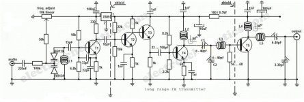
long-range-fm-transmitter1.jpgT1 = T2 = T3 = T4 = BF199
T5 = 2N3866, 2N4427 or 2SC1970 for 1Watt / 2SC1971, BLX65, BLY81, KT920A or 2N3553 for 1.5 to 2W power.
L1 = 5 turns / 0.6mm / 4mm silvered copper
L2 = 6 turns / 0.8mm / 6mm enamelled copper
L3 = 3 turns / 1mm / 7mm silvered copper
L4 = 6 turns / 1mm / 6mm enamelled copper
L5 = 4 turns / 1mm / 7mm silvered copper
Use silvered copper for L3 and L5 if you want to obtain better characteristics.


[h=3]Adjustments of the long range transmitter[/h]Start by construction the oscillator stage, solder a small wire to T1 10pF capacitor out and listening to a fm receiver, trim the 10k pot untill you can “hear​
 

reza_476

کاربران vip(افتخاری)
vip افتخاری
کاربر
2009-10-19
4,007
45,272
ایران
و اینهم یکی دیگر:
[h=1]1.5 Watt 1-2 km Range FM Transmitter[/h]

[h=2]Description[/h]
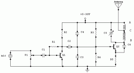
Here is a well designed FM transmitter circuit that works effectively in 1 - 2 km range. Input source is an electret condenser microphone and signal gain can be adjusted by using the potentiometer P1. You can easily prepare the PCB by using any PCB editor and apply it to the board by using the ironing method. The coils and the antenna can be designed as a part of the PCB made up of the copper area.​
[h=2]Parts List[/h]
R1=220K
R2=4.7K
R3,R4=10K
R5=100ohm
C1,C2=4.7uF Electrolytic
C3,C4=1nF
C5=2-15pF
C6=3.3pF
Q1=BC547C
Q2=2N2219A
P1=25K
MIC=Electret Condenser Type

1_5w_fm_transmitter_with_1-2km_range.gif
 
وضعیت
موضوع بسته شده است و نمی‌توان پاسخ جدیدی فرستاد.
بالا